
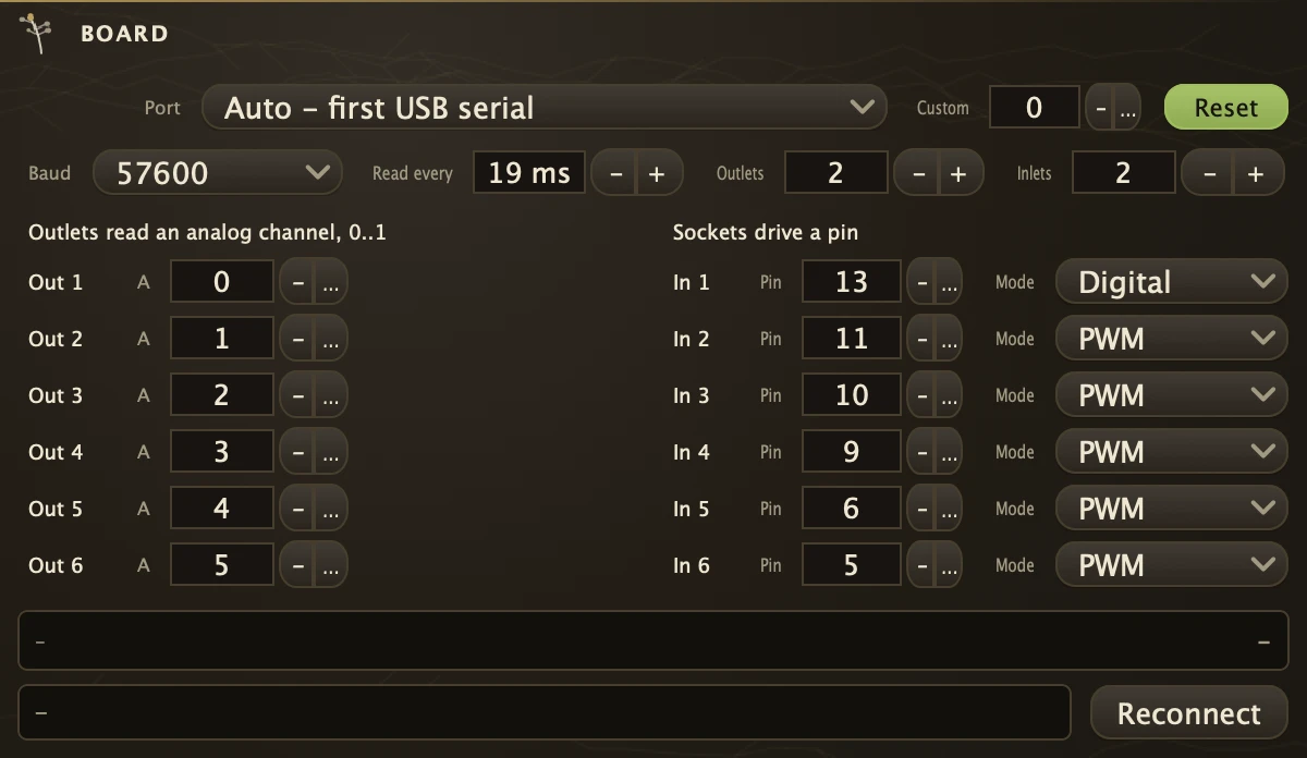
A microcontroller board on a serial cable: its analog inputs come out as control outlets and its sockets drive pins on the board.
Flash the board once with the standard pin-control sketch that ships as an example with the board's own editor, plug it in and pick a preset for your board. Each outlet reads one analog channel as 0 to 1, whatever the board's resolution, so a potentiometer or a light sensor on A0 becomes outlet 1: cord it onto a Number to watch it or onto a Gain's socket to shape a level. Each socket drives one pin, switching it or dimming it. The board is read away from the audio path, and replugging reconnects on its own. Board is also a control source, so any parameter's right-click menu offers Control with Board. A board without the standard sketch is left to boot for three seconds and then spoken to anyway; a board running a sketch of your own belongs on SerialIn and SerialOut instead.
The readout
The line under the outlets says where the box stands: looking for a device, waiting for the port, booting, talking, pins mapped. The outlets sit at zero until the board has come up. The presets set which channels the outlets read and which pins the sockets drive; the board itself then reports what each pin can do, so a board that is not on the list still works with the pins typed in by hand.
Parameters
| Device | Which serial device the board is on. Auto picks the first USB serial device found; the rest of the list is every device present. Any number of Board, SerialIn and SerialOut boxes can share one port. |
| BaudRate | The port's speed. The standard sketch opens at 57600, the default here; change it only if you changed the sketch. |
| Custom | Any rate not on the list. Zero leaves BaudRate in charge. |
| Reset | On, opening the port reboots the board the way its editor does, which is what the standard sketch expects. Off keeps the board running across a reconnect. |
| Reconnect | Closes the port and opens it again for every box sharing it. Use it when a board has stopped answering. |
| Rate | How often the board samples and sends its analog inputs, in milliseconds. 19 is the sketch's own default; lower is livelier and busier on the wire. |
| Outlets | How many outlets the box shows, one to six. |
| Inlets | How many sockets the box shows, one to six. |
| In1 | The first socket, and the level its pin gets when nothing is corded onto it. And so on for 2 to 6. |
| Analog1 | The analog channel outlet 1 reads, 0 to 15. Out of the box outlet 1 reads A0, outlet 2 reads A1, and so on for 2 to 6. |
| Pin1 | The board pin socket 1 drives. And so on for 2 to 6. |
| Mode1 | Digital takes the pin high when the socket is above 0.5 and low otherwise. PWM sets the pin's duty cycle from the socket's 0 to 1; only some pins can do PWM, and the presets put those on sockets 2 to 6. And so on for 2 to 6. |
| Port | An explicit device path, which overrides Device while it is set. Normally left empty. |
Recipe
| Sensor to filter | Wire a potentiometer to A0, pick your board's preset and check the readout says talking. Right-click a Filter's Frequency, choose Control with Board out1, and the knob follows the pot. Cord a Follower's env onto In2 with Mode2 on PWM and the LED on that pin dims with the music. |